Presentation
The BusVoodoo is a multi-protocol debugging adapter. This tool allows to quickly communicate with various other electronic devices.
The software is embedded in the adapter. Just plug the device over USB and use your favourite serial terminal. Connect the electronics you want to debug on the pins of the adapter and start communicating with it using the embedded software. And if you still prefer to use a dedicated adapter for more specific or complex tasks, there are alternative firmwares.
Features
The BusVoodoo adapter comes in two flavours: light and full
BusVoodoo light
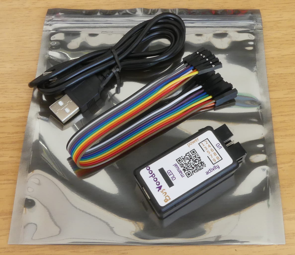
The BusVoodoo light provides everything to works with TTL/CMOS protocols using the 2x5 pins I/O connector.
It comes in a case, with a USB cable (mini-USB), and a 10 pins female to female jumper cable (20 cm).
BusVoodoo full
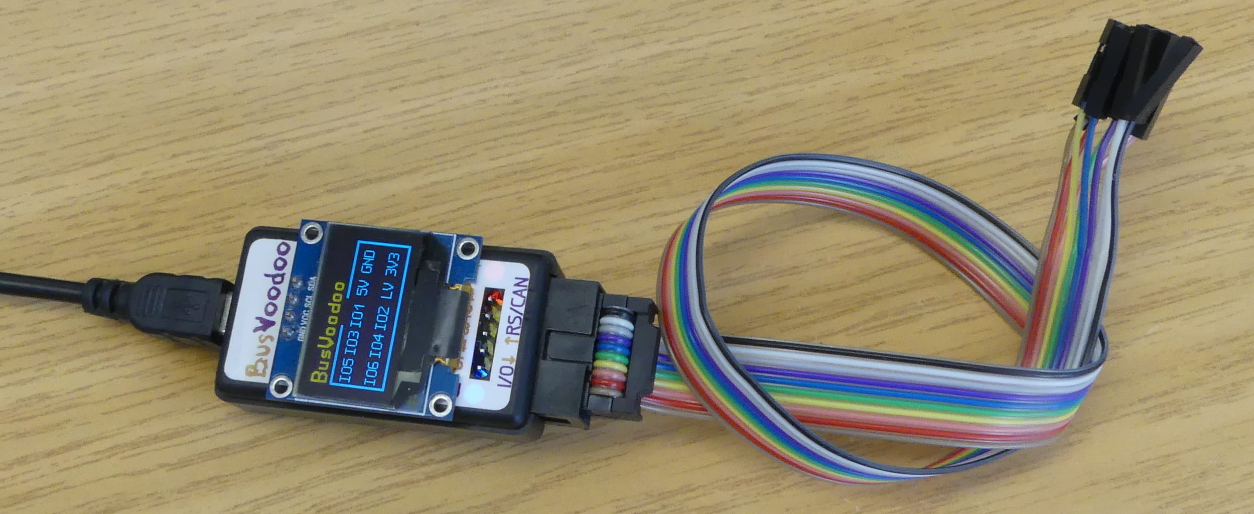
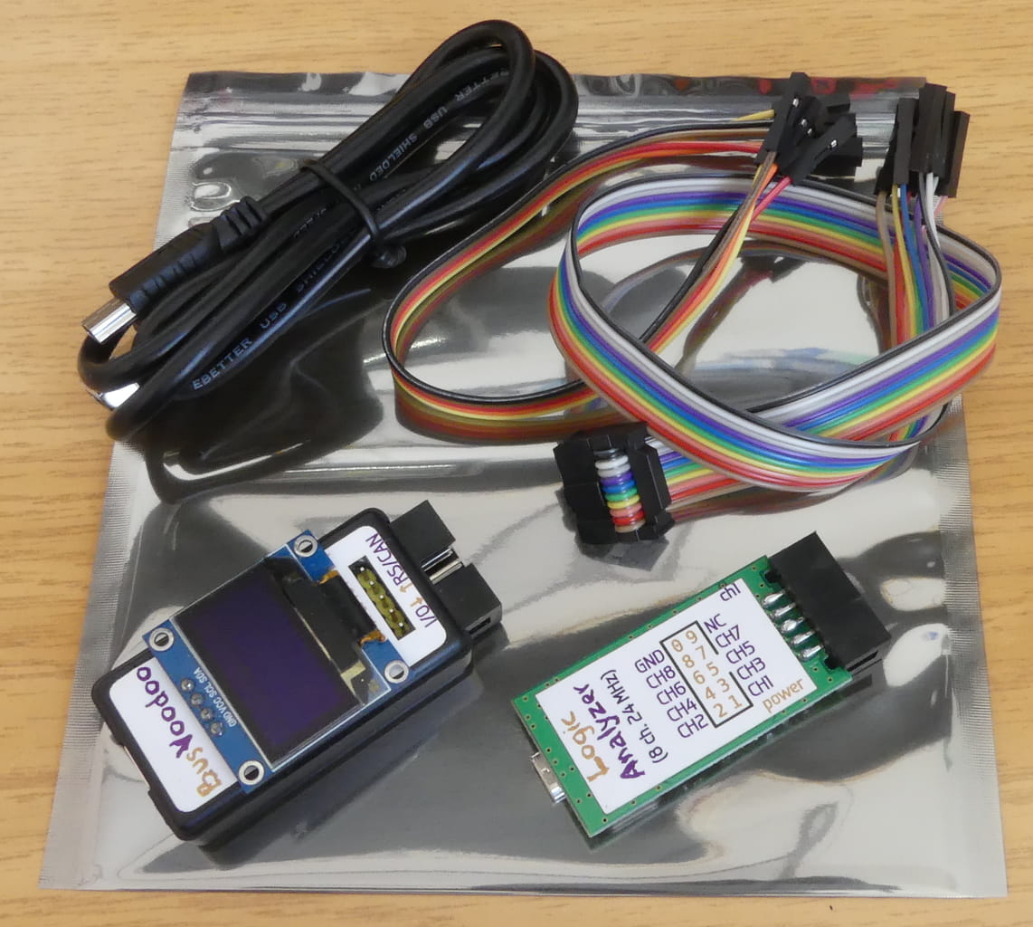
The BusVoodoo full adds to the BusVoodoo light a high voltage output, RS-232, RS-485/RS-422, and CAN support through a dedicated RS/CAN connector. An OLED display will also show the pinout for the current protocol used.
It comes with 5 pins female to female jumper cable (20 cm), a proper 2x5 coloured IDC to 10 pins jumper cable (30 cm), and a logic analyser (8 channels, 24 MHz). And most importantly, it comes with protocol support. If there is an issue with the current software, or a protocol or feature is missing, you can request this to be fixed (as long as the hardware supports it).
Hardware capabilities
Device properties:
-
compact case: 56.0x27.7x14.7 mm
-
USB host connection: USB 2.0, mini-B, full speed (11 Mb/s)
-
I/O connector: 10-pin header for TTL/CMOS protocol (0 to 5.5V)
-
RS/CAN connector: 5-pin header for other common protocol (only on BusVoodoo full)
-
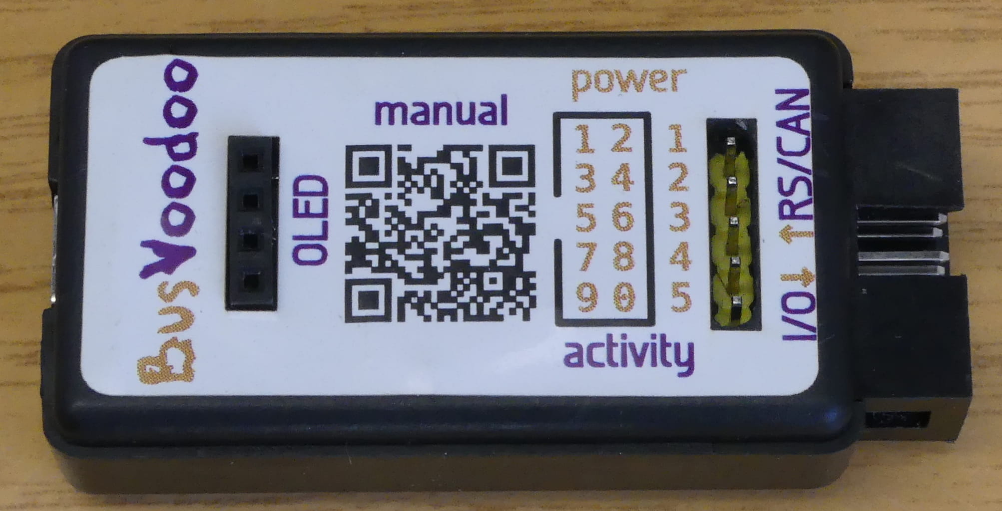
OLED display: to show the pinout for the current protocol used (only on BusVoodoo full)
-
power (red) and activity (red/blue) LEDs
I/O connector:
-
2x5 pins header (IDC, 2.54 mm pitch)
-
5 V output (up to 400 mA), software switchable
-
3.3 V output (up to 200 mA), software switchable
-
0 to 4.8 V and 5 V adjustable voltage output (up to 300mA), connected to the embedded pull-up resistors (target device voltage can be input), and 0 to 6 V ADC
-
6 I/O pins, 3.3 V in push-pull mode (protected using 100 Ohm resistors), 1.6 to 5.5 V in open-drain mode using strong 2 kOhm embedded pull-up resistors (with internal adjustable voltage regulator or external power source)
RS/CAN connector (only on BusVoodoo full):
-
1x5 pin header (2.54 mm pitch)
-
3.3 to 24 V adjustable voltage output (up to 30 mA), to program devices using high voltages
-
RS-232 port (with hardware flow control)
-
RS-485/RS-422 port (not terminated)
-
CAN port (not terminated)
Origin and purpose
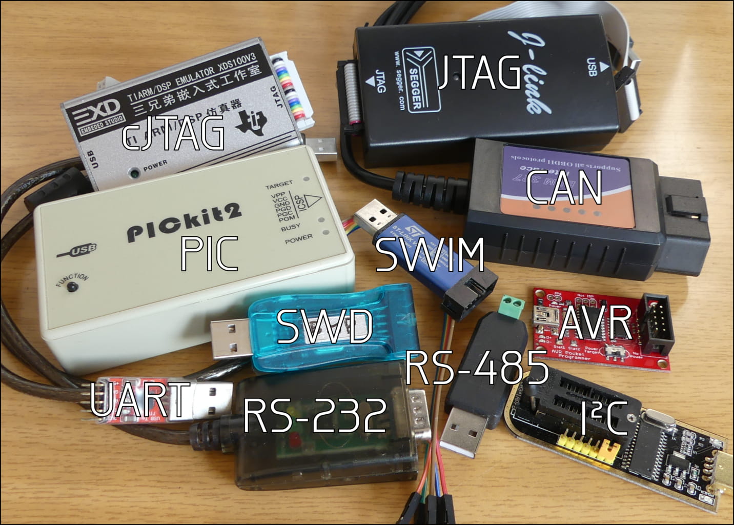
Whenever I go to conferences I like to take apart devices I find there. The problem is that I can’t always bring bring all the adapters: UART, JTAG, I2C, RS232 … there are just too many, and in the end I never have the right one.
The alternative I found was just to take a development board with a general purpose micro-controller (a feature-rich STM32F1). This comes with peripherals for the major protocols (UART, SPI, I2C) and for the others I just implement them is software. The drawback is that I need to program the micro-controller every time, reference manual at hand, and this takes at least 30 not so exciting minutes. Now comes the BusVoodoo.
The BusVoodoo is a USB adapter with pre-programmed support for numerous protocols, allowing to communicate with other device without hassle. It appears as a serial device. Use a terminal emulation program to connect to it (e.g. picocom for Linux, putty for Windows), configure the protocol using the built-in menu, you are ready you are to communicate with other devices.
Since the beginning of electronics probably every engineer developed his own dedicated programming or debugging tool. This is just mine, packed with features and made available for all.
While it is packed with features, it is just a debugging and hacking tool and you are the brain behind it. You still need to know about electronics (e.g. the difference between push-pull and open-drain driving modes) and have a basic understanding of the protocol you want to talk.
It comes with no network connectivity. Its purpose is to debug and hack devices locally, not to provide a gateway to remotely control other devices.
The BusVoodoo is a compact device which supports a lot of protocols, which makes it quite versatile. But it is not intended to replace all the other special purpose adapters (USB to UART, JTAG, …) which probably can better solve specific tasks because their are: simpler, more powerful, faster, more stable, cheaper, or more available. Thus the BusVoodoo is a good choice to start with, but if you want better performances switch to a device designed for each particular task. And if you want to debug high-speed protocols you will need a complete different class of adapter.
This device is not the result of a collaborative work in a forum with 1000 pages and chaotic status. I developed it and actively support it. I actually also use it in my everyday work, and thus have an interest of keeping the quality high. Nothing prevents you from building it yourself or forking it though. Both hardware and software are open-source and available here, and you are welcome to submit bug reports or patches.
Getting it
The BusVoodoo is still under development. Samples are distributed to selected reviewers in order to get feedback. Once the reported issues are taken care of, it will be available to anyone else.
If you are impatient, you can still get the hardware sources and produce your own board.
Manual
Further information about the BusVoodoo is available in the manual.