Presentation
The BusVoodoo is a multi-protocol debugging adapter. This tool allows to quickly communicate with various other electronic devices.
The software is embedded in the adapter. Just plug the device over USB and use your favourite serial terminal. Connect the electronics you want to debug on the pins of the adapter and start communicating with it using the embedded software. And if you still prefer to use a dedicated adapter for more specific or complex tasks, there are alternative firmwares.
Features
The BusVoodoo adapter comes in two flavours: light and full
BusVoodoo light
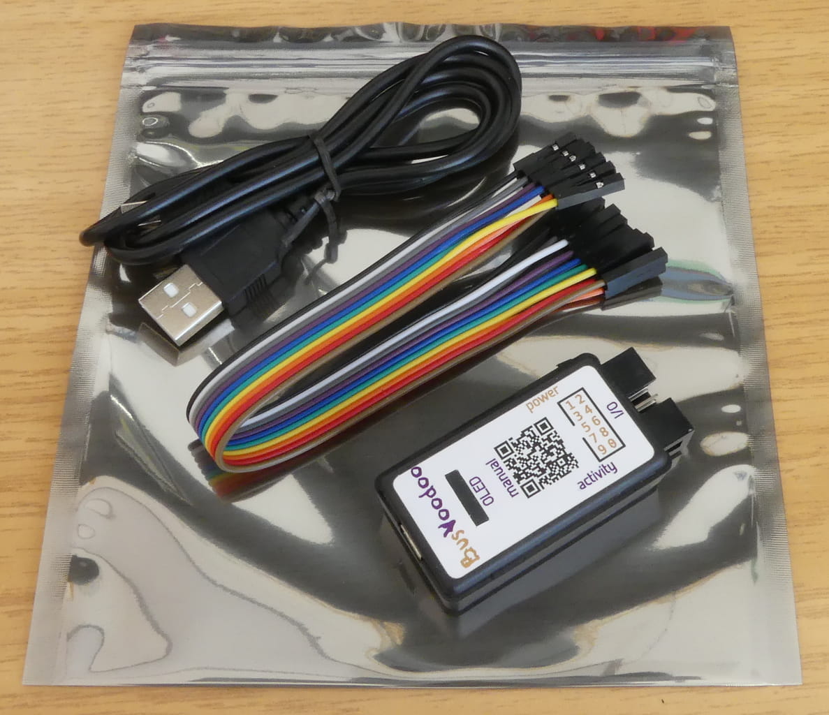
The BusVoodoo light provides everything to works with TTL/CMOS protocols using the 2x5 pins I/O connector.
It comes in a case, with a USB cable (mini-USB), and a 10 pins female to female jumper cable (20 cm).
BusVoodoo full
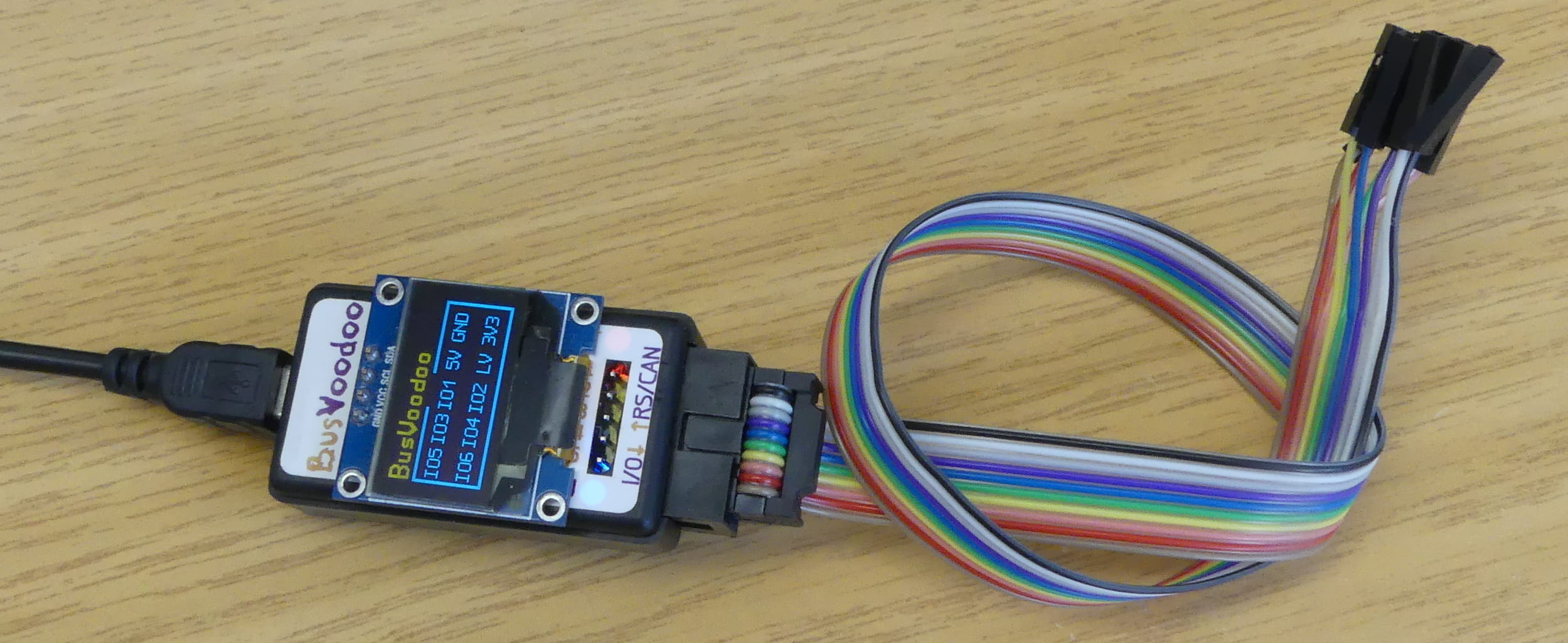
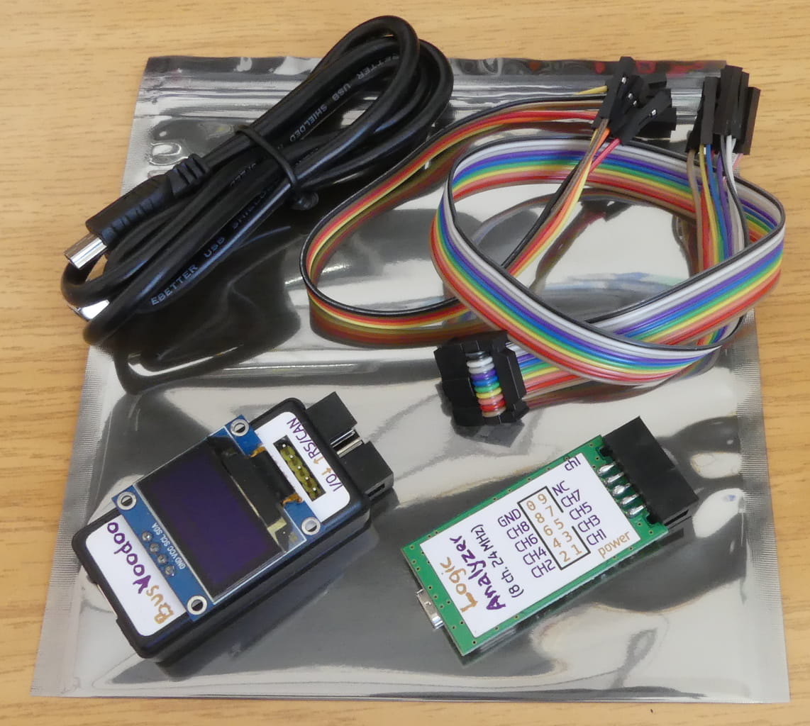
The BusVoodoo full adds to the BusVoodoo light a high voltage output, RS-232, RS-485/RS-422, and CAN support through a dedicated RS/CAN connector. An OLED display will also show the pinout for the current protocol used.
It comes with 5 pins female to female jumper cable (20 cm), a proper 2x5 coloured IDC to 10 pins jumper cable (30 cm), and a logic analyser (8 channels, 24 MHz). And most importantly, it comes with protocol support. If there is an issue with the current software, or a protocol or feature is missing, you can request this to be fixed (as long as the hardware supports it).
Hardware capabilities
Device properties:
-
compact case: 56.0x27.7x14.7 mm
-
USB host connection: USB 2.0, mini-B, full speed (11 Mb/s)
-
I/O connector: 10-pin header for TTL/CMOS protocol (0 to 5.5V)
-
RS/CAN connector: 5-pin header for other common protocol (only on BusVoodoo full)
-
OLED display: to show the pinout for the current protocol used (only on BusVoodoo full)
-
power (red) and activity (red/blue) LEDs
I/O connector:
-
2x5 pins header (IDC, 2.54 mm pitch)
-
5 V output (up to 400 mA), software switchable
-
3.3 V output (up to 200 mA), software switchable
-
0 to 4.8 V and 5 V adjustable voltage output (up to 300mA), connected to the embedded pull-up resistors (target device voltage can be input), and 0 to 6 V ADC
-
6 I/O pins, 3.3 V in push-pull mode (protected using 100 Ohm resistors), 1.6 to 5.5 V in open-drain mode using strong 2 kOhm embedded pull-up resistors (with internal adjustable voltage regulator or external power source)
RS/CAN connector (only on BusVoodoo full):
-
1x5 pin header (2.54 mm pitch)
-
3.3 to 24 V adjustable voltage output (up to 30 mA), to program devices using high voltages
-
RS-232 port (with hardware flow control)
-
RS-485/RS-422 port (not terminated)
-
CAN port (not terminated)
Installation
The BusVoodoo appears as a serial port over the USB port using the USB communication device class (CDC). Most operation systems already include a diver for this standard USB class.
Windows 7
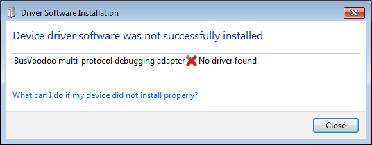
Microsoft Windows 7 already includes the USBSER.sys driver to support USB serial ports, but you sill need to indicate this driver needs to be used for the BusVoodoo device using an inf file.
When plugged in, Windows shouldn’t automatically find the appropriate driver:
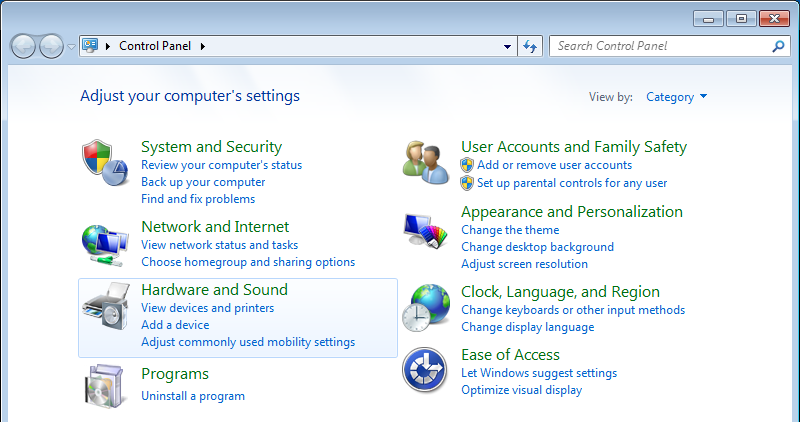
To tell Windows which driver should be used for this device:
-
open the Control Panel and select Hardware and Sound
-
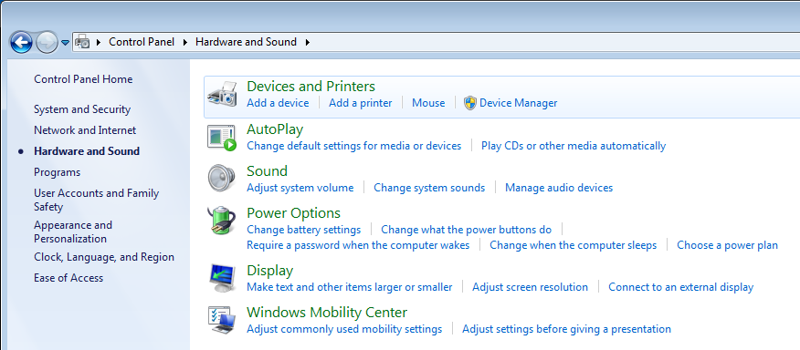
open the Device Manager
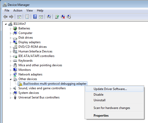
-
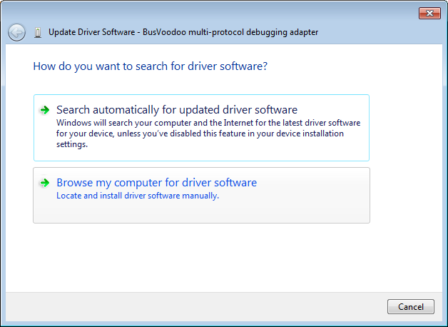
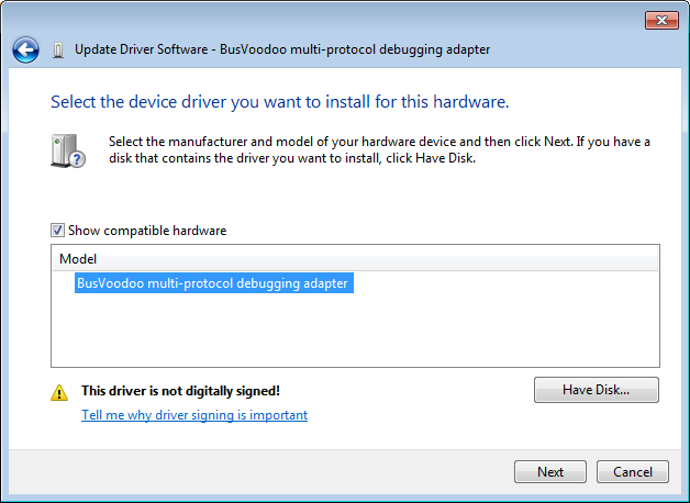
right click on the BusVoodoo multi-protocol debugging adapter to Update Driver Software…
-
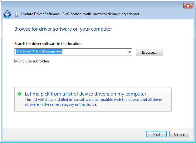
select Browse my computer for driver software
-
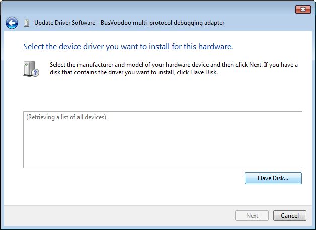
select Let me pick from a list of device drivers on my computer
-
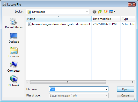
click on Have Disk…
-
select the previously downloaded inf file
-
select the BusVoodoo multi-protocol debugging adapter driver
-
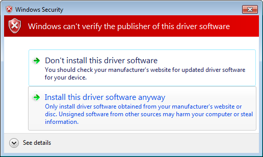
since this file is not signed, you have to confirm the you want to Install this driver software anyway. But no worries, the inf file is only telling to use the Windows USBSER.sys driver for the BusVoodoo device
-
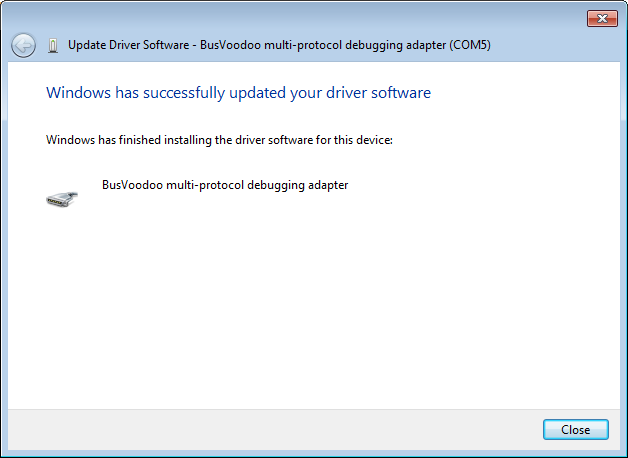
the driver update should be successful
-
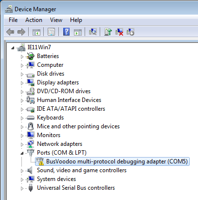
now you can also see which COM port has been allocated to this device
|
Tip
|
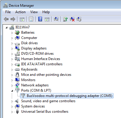
To find out which which COM port has been allocated to the BusVoodoo (i.e. in case the driver got reinstalled because the device is plugged in another USB port), open the Device Manager and look for the BusVoodoo device under Ports (COM & LPT). |
Windows 10
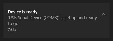
Microsoft Windows 10 already includes the driver to support USB serial ports and will install it directly when the BusVoodoo is plugged in. The notification will also tell you which COM port has been allocated to this device.
|
Tip
|
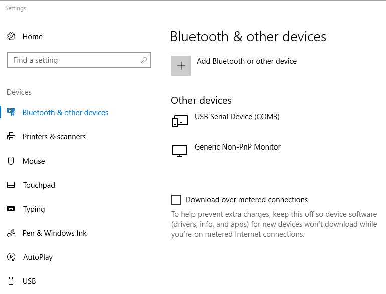
To find out which COM port has been allocated to the BusVoodoo (i.e. in case the driver got reinstalled because the device is plugged in another USB port), open the Settings application and look for USB Serial Device (COMx) in the Bluetooth & others devices tab. |
Linux
Linux comes with the cdc_acm module driver for USB devices using the CDC ACM class. A /dev/ttyACMx character device will automatically appear once the BusVoodoo is plugged in, with x being the next available number.
|
Tip
|
To know which /dev/ttyACMx is allocated for the BusVoodoo device, you can run the following command in a terminal just before plugging in the device and see the allocation (use CTRL+C to quit). |
journalctl -f | grep -B 2 cdc_acm

kernel: usb 2-3.3: Product: BusVoodoo multi-protocol debugging adapter
kernel: usb 2-3.3: Manufacturer: CuVoodoo
kernel: cdc_acm 2-3.3:1.0: ttyACM0: USB ACM device
|
Tip
|
Instead of figuring out which /dev/ttyACMx is the correct one, use the identified serial device /dev/serial/by-id/usb-CuVoodoo_BusVoodoo_*-if00. Use the complete id including the serial if you have multiple BusVoodoo device connected at the same time. |
To be able to access serial port the user needs to be in the right group. On Debian based distributions this is dialout. On Arch this is uucp. To find out which group the user needs to be in to be able to access the serial port run the following command and look for the Gid:
stat /dev/ttyACM0

  File: /dev/ttyACM0
  Size: 0               Blocks: 0          IO Block: 4096   character special file
Device: 6h/6d   Inode: 7724046     Links: 1     Device type: a6,0
Access: (0660/crw-rw----)  Uid: (    0/    root)   Gid: (   20/ dialout)
To add the current user to this group run:
sudo usermod -a -G dialout $USER
|
Caution
|
For this change to take effect the user must log out and back in. |
|
Tip
|
To view in which groups the current user is, run id. |
Connection
The BusVoodoo doesn’t require a dedicated software to be operated. Once you know which serial port have been allocated for the BusVoodoo, you can use any serial terminal software to connect to it. Since it uses native USB, baud rate and other serial port settings are not relevant (e.g. you can pick any).
Windows
PuTTY
PuTTY is mainly a SSH client, but can also open serial port. One advantages is that it also comes as portable binary.
Select the Connection type Serial and set the right COM port in Serial line.
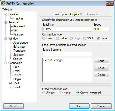
Then open the port and off you go.
|
Tip
|
You can save the settings as Default Settings so you don’t have to set the serial port every time you use PuTTY. |
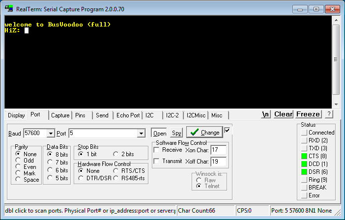
RealTerm
RealTerm is another popular serial terminal program.
Select the right COM port in the Port drop down list under the Port tab and click on Open.
|
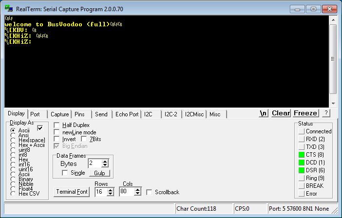
Important
|
The BusVoodoo menu uses ANSI escape codes. For these to be displayed correctly select Ansi in the Display As box under the Display tab. |
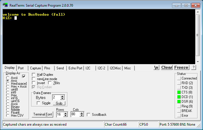
Else you will see all escape codes instead of the final rendering.
Linux
I favour picocom because of its simplicity, but you can also use the feature-rich minicom, the lightweight microcom, or even the ancient screen. All are Command Line Interface programs and can be installed using the local package manager of your Linux distribution. For Debian based distributions run sudo apt install picocom (replace picocom with your choice). Then open the serial port using picocom /dev/serial/by-id/usb-CuVoodoo_BusVoodoo_*-if00, provided you have the rights to access it (check the help or man page for the other serial terminal programs).
Usage
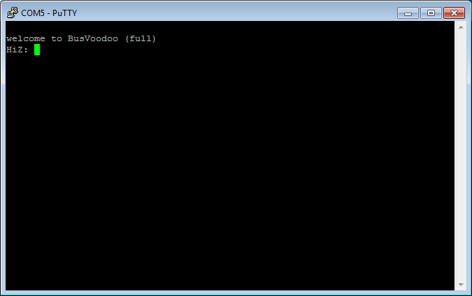
Once connected to the BusVoodoo, you can use the embedded software to debug the target hardware.
The prompt allows entering commands. Enter help to get the commands supported in the current mode. Some commands are available in all modes while others are mode specific.
Modes correspond to protocols. The current mode is displayed at the beginning of the command prompt. BusVoodoo starts in the high impedance mode (HiZ). This mode corresponds to no protocol and all I/O pins are left floating. You can still enable the power outputs.
To list the supported modes enter mode. To switch mode enter mode <mode>, where <mode> is one of the listed modes. You can quit the mode and switch back to the default HiZ mode using CTRL+D. The name and pinout of the connector of each mode is displayed on the OLED screen (if present) but can also be displayed in the terminal using the pinout command.
|
Note
|
most commands also have a one letter shortcut. |
The prompt supports ANSI escape codes to improve interaction:
-
use the Up, Down, Page Up, and Page Down keys to browse through the history of commands
-
commands can be edited using the Left, Right, Home, End, Backspace, Delete, and Insert keys
-
to cancel a command use CTRL+C
Protocols
The BusVoodoo implements numerous low-speed protocols. The hardware is only designed for signal speeds up to 20 MHz. The signals can be driven using 3.3 V in push-pull mode, or 1.6 to 5.5 V in open-drain mode with 2 kOhm embedded pull-up resistors (which can be increased using an external resistor on the LV low voltage pin and external target voltage). All signal are protected with 100 Ohm series resistors.
| protocol | implementation | comment | status |
|---|---|---|---|
UART |
hardware |
with baud rate and configuration detection, flow control: hardware RTS/CTS, baud rate: 1200-2000000 bps, data: 5-8 bits, parity: none/even/odd/mark/space, stop: 0.5-2 bits |
supported |
SPI |
hardware |
with slave select |
supported |
I²C |
hardware |
with embedded pull-up resistors |
supported |
I²S |
hardware |
with master clock |
planned |
SD/eMMC |
hardware |
with 1 or 4 data lines |
WiP |
SMBus |
hardware |
with embedded pull-up resistors |
planned |
LIN |
hardware |
needs external level shifter for 12 V support |
planned |
ISO-7816 |
hardware |
planned |
|
1-Wire |
software |
with ROM search, can provide power over data line |
supported |
MicroWire |
software |
planned |
|
IR |
software |
various InfraRed protocols |
planned |
JTAG |
software |
use BMP alternative for now |
planned |
SWD |
software |
use BMP alternative for now |
WiP |
cJTAG |
software |
planned |
|
Note
|
No matter which protocol you are using, the hardware has been designed to provide one additional UART port. |
| protocol | implementation | comment | status |
|---|---|---|---|
WS2812b |
software |
LED control protocol |
planned |
DHT11/DHT22 |
software |
humidity and temperature sensor protocol |
planned |
TM1637 |
software |
7-segment display protocol |
planned |
The BusVoodoo in full flavour also supports non-TTL/CMOS protocols.
| protocol | implementation | comment | status |
|---|---|---|---|
RS-232 |
hardware |
with baud rate and configuration detection, flow control: hardware RTS/CTS, baud rate: 1200-2000000 bps, data: 5-8 bits, parity: none/even/odd/mark/space, stop: 0.5-2 bits |
supported |
RS-485 |
hardware |
no termination resistor, with baud rate and configuration detection, baud rate: 1200-2000000 bps, data: 5-8 bits, parity: none/even/odd/mark/space, stop: 0.5-2 bits |
supported |
RS-422 |
hardware |
no termination resistor, with baud rate and configuration detection |
supported |
CAN |
hardware |
no termination resistor |
planned |
Flashing
Since the BusVoodoo software is under active development it is recommended to check the manual for new supported protocols and flash the latest firmware.
Firmwares are specific to the BusVoodoo hardware version. To know the hardware version of the BusVoodoo connect to the BusVoodoo and enter the version command in HiZ mode. This should be a letter (or 0 for the first prototypes). Use this letter to get the corresponding firmware (e.g. BusVoodoo-firmware-vA_latest.zip for hardware version A).
The firmware version is simply the date at which it was built. To know the firmware version flashed on the BusVoodoo connect to the BusVoodoo and enter the version command in HiZ mode. The version of the latest firmware is the date of the BusVoodoo-firmware-vX_latest.zip file found here (X being the letter of your hardware version).
USB DFU
The application firmware can be flashed over USB using the Device Firmware Upgrade (DFU) capabilities. To flash the application firmware we will use the dfu-util software.
Windows
To flash an application firmware over USB DFU under Windows:
-
connect to the BusVoodoo and enter the bootloader command in HiZ mode. This will switch the BusVoodoo from the application runtime to the bootloader DFU mode. The power and activity LEDs should be both red. In the hardware manager the COM port should be marked a not being able to start.
-
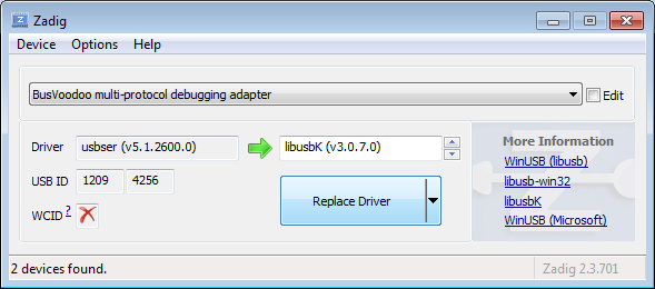
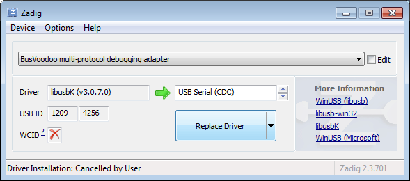
using Zadig, switch the USB driver to allow dfu-util to access the BusVoodoo USB device
-
go in the option menu to enable viewing all USB devices
-
select the BusVoodoo multi-protocol debugging adapter in the drop down list
-
select libusbK as replacement USB driver
-
click on Replace Driver
-
-
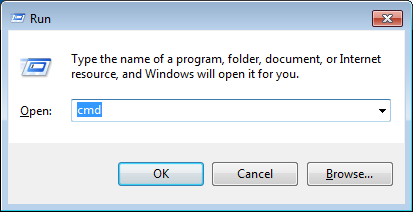
press on the Windows and R keys on the keyboard to start the run windows.
-
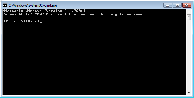
enter to cmd command and press OK to start the command terminal
-
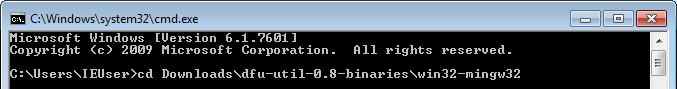
download and extract dfu-util, and go to the directory with the dfu-util.exe file using the cd command (use the 32-bit binaries for 32-bit Windows and 7-zip to extract it).
-
download and extract the latest firmware and copy the application.bin file next to the dfu-util.exe file
-
flash the application.bin application firmware using dfu-util.exe with the following command
dfu-util.exe --device 1209:4256 --download application.bin
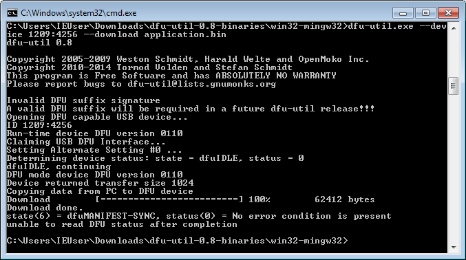
-
while flashing the firmware, the activity LED will blink blue, and once flashing is completed the BusVoodoo will restart ant the activity LED should stay blue
-
now you can replace back the USB driver to USB Serial (CDC) (e.g. usbser) using Zadig so you can access the serial port again
Linux
Install dfu-util using the distribution package manager. To do so on Debian based distributions run the following command.
sudo apt install dfu-util
Now you are ready to flash the firmware using the following command, with application.bin being the path to the corresponding file in the firmware archive.
sudo dfu-util --device 1209:4256 --download application.bin
To avoid using sudo every time you update the firmware you can grant access permissions to the USB device to the current user. For that we will create the plugdev group (often used when developing for devices) and add a udev rules for the BusVoodoo device. This requires to be done only once.
# create plugdev group
sudo groupadd plugdev
# add current user to plugdev group
sudo usermod -a -G plugdev $USER
# add udev rule for BusVoodoo
sudo tee -a /etc/udev/rules.d/60-plugdev.rules << EOF
# BusVoodoo multi-protocol debugging adapter
SUBSYSTEM=="usb", ATTR{idVendor}=="1209", ATTR{idProduct}=="4256", MODE="664", GROUP="plugdev"
EOF
# reload rules
sudo udevadm control --reload-rules
sudo udevadm trigger
|
Caution
|
For the user to effectively be in the plugdev group the user must log out and back in. |
DFU bootloader
dfu-util should automatically switch the BusVoodoo from the application runtime mode to the bootloader DFU mode so the application can be flashed thanks to the bootloader.
If for some reasons this switch does not happen you can connect to the BusVoodoo embedded software and enter the bootloader command in HiZ mode.
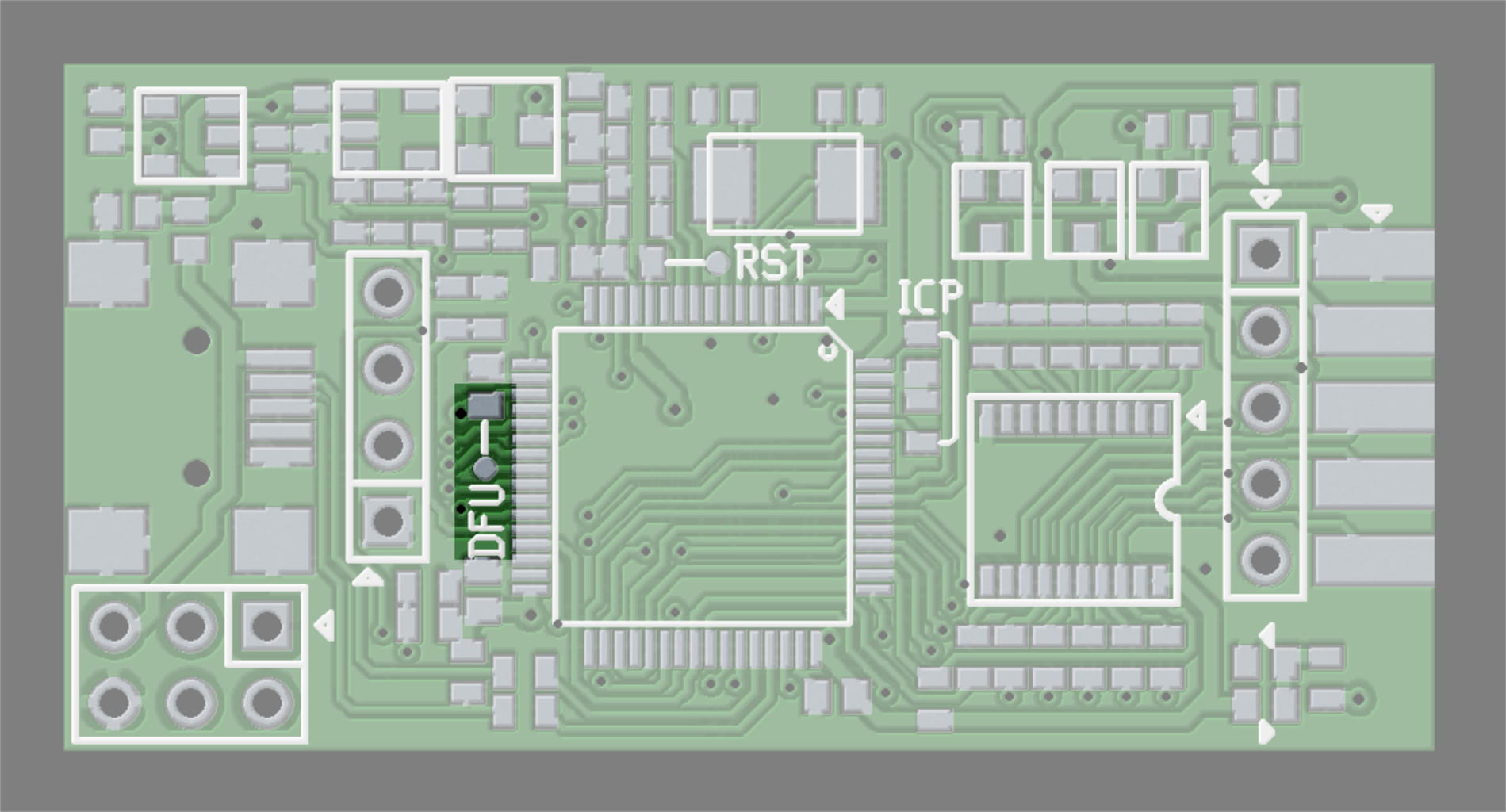
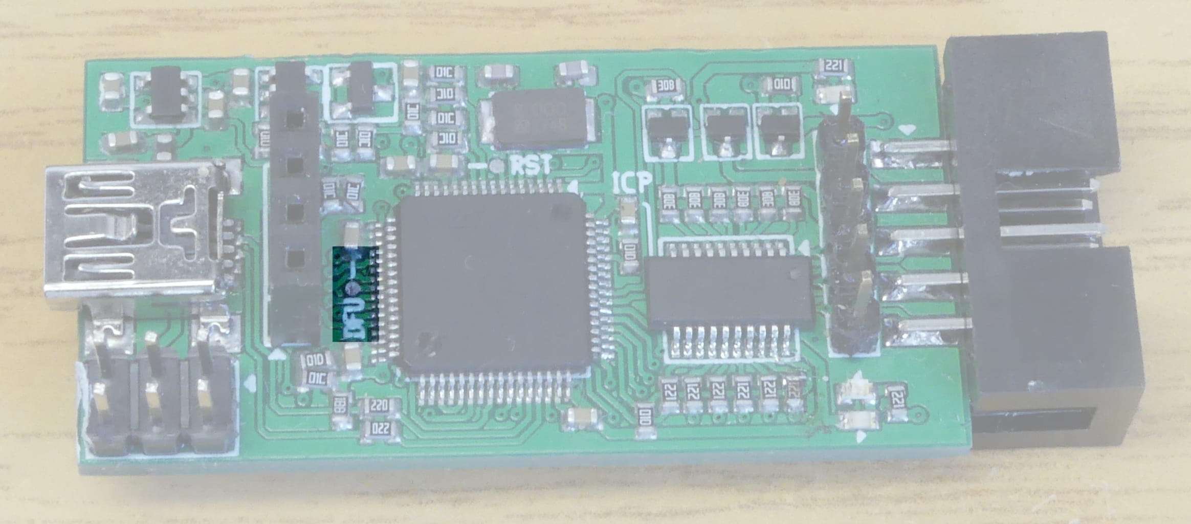
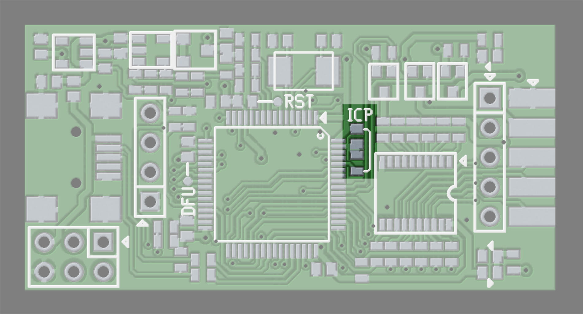
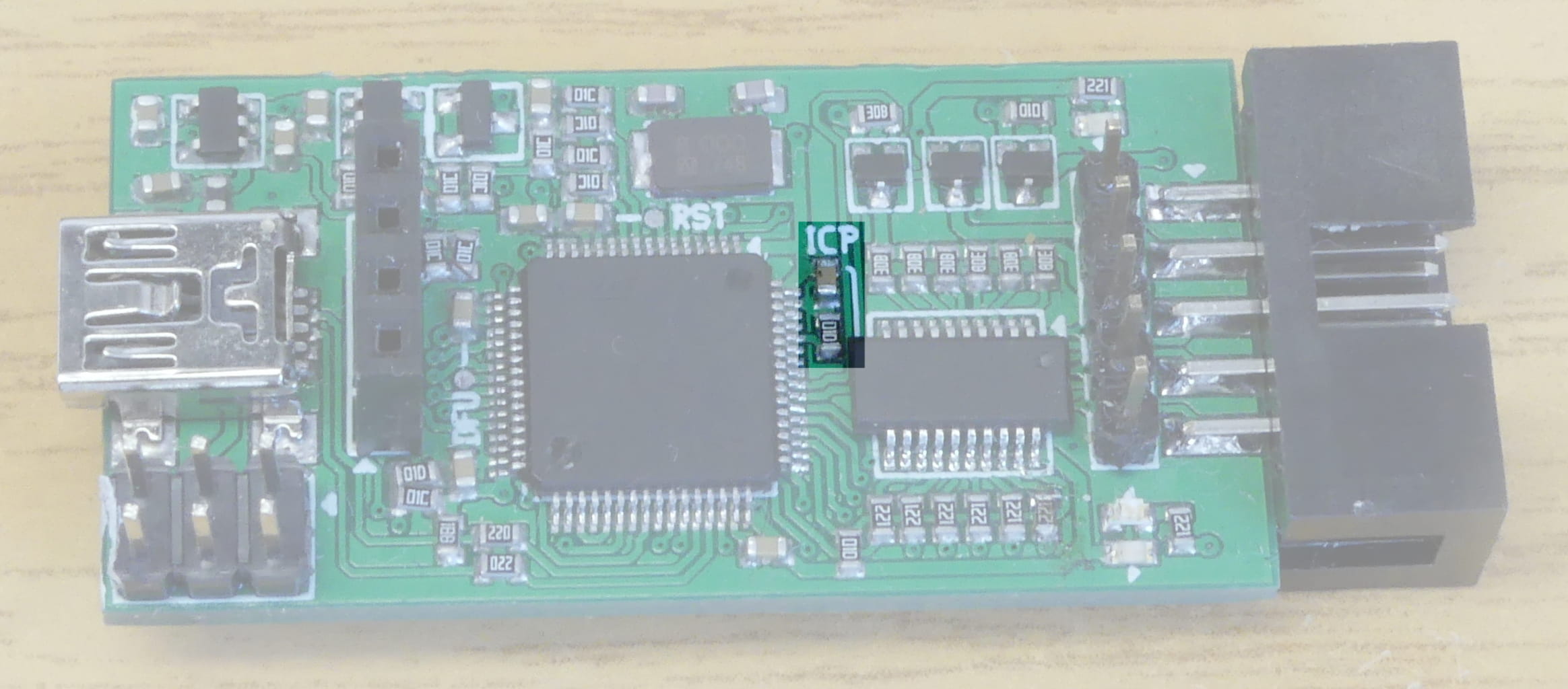
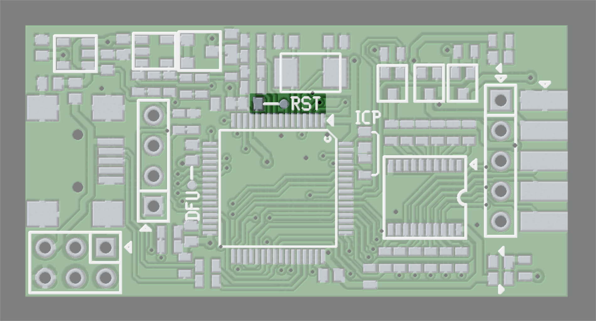
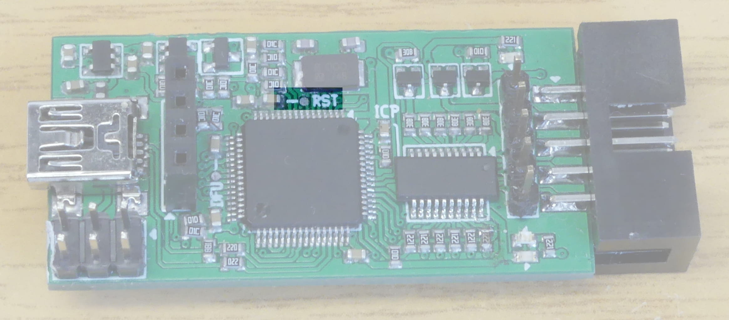
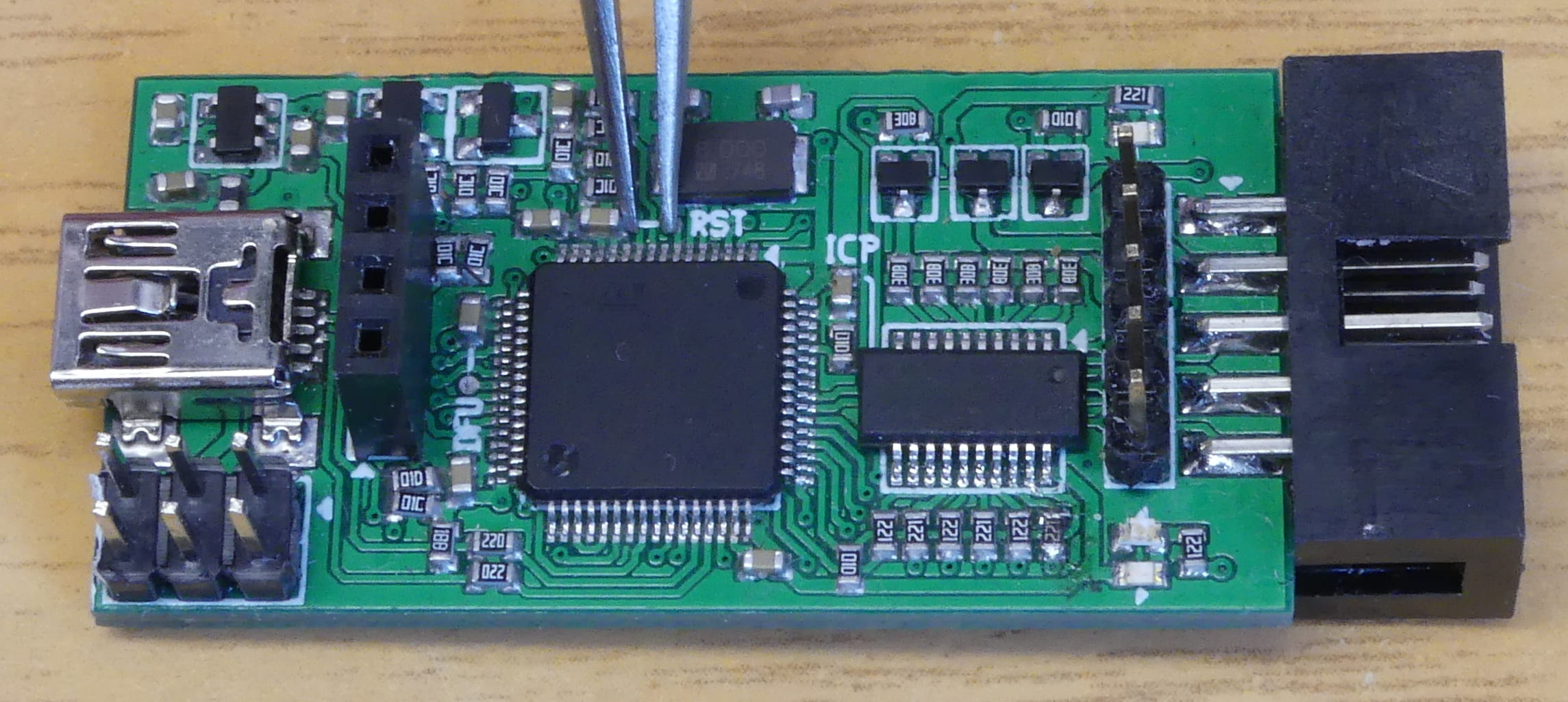
In case you can’t connect to BusVoodoo or the application firmware is broken, you can force the device to start in DFU mode. For that open the case and short the DFU test point to the 3.3 V pad on the nearby capacitor while powering the device (e.g. using some tweezers).
|
Caution
|
BusVoodoo version 0 has a different DFU pin. |
When the bootloader DFU mode is started, the power and activity LEDs are both red. Run dfu-util to flash the application firmware. While flashing the application firmware, the activity LED will blink blue. Once the application firmware is flashed and started successfully the activity LED will stay on blue.
UART bootloader
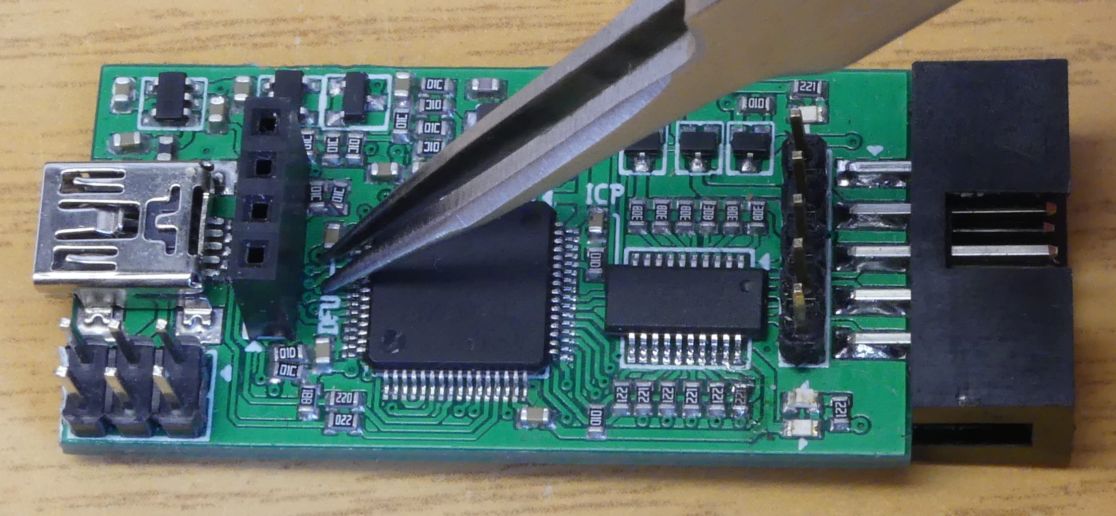
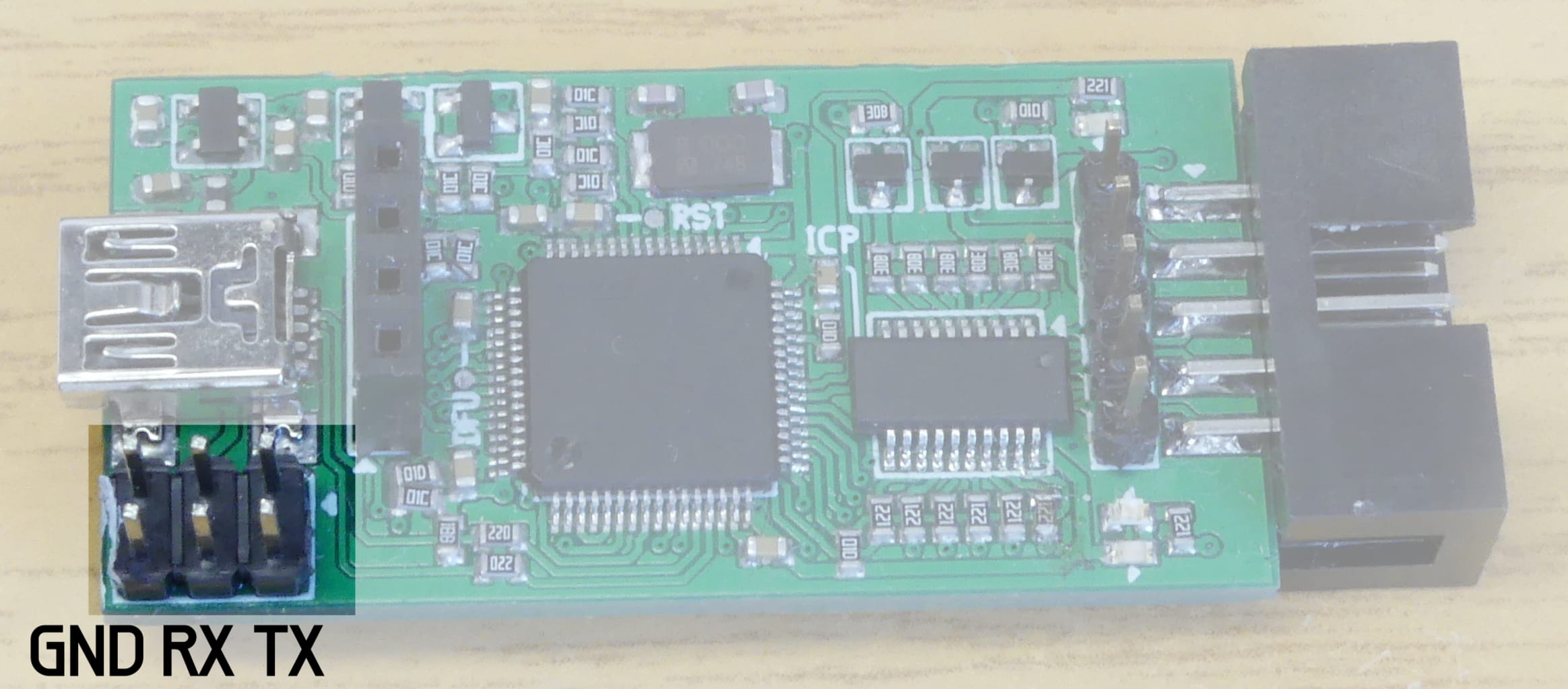
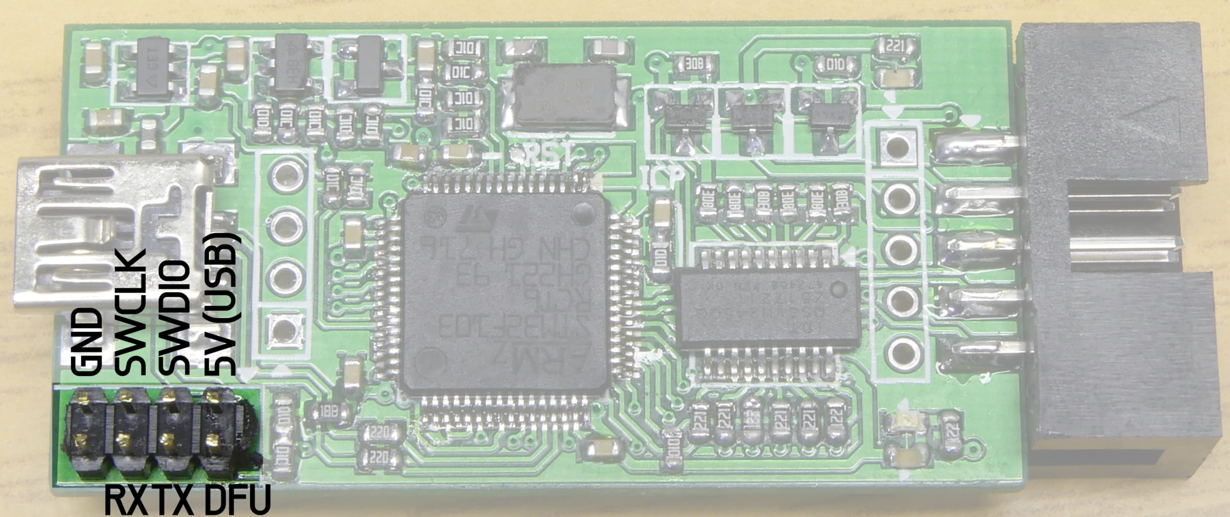
It is possible to replace or update the USB DFU bootloader using the micro-controller’s embedded UART bootloader. For that open the case and short the ICP pad on a resistor to the 3.3 V pad on the nearby capacitor while powering the device (e.g. using some tweezers).
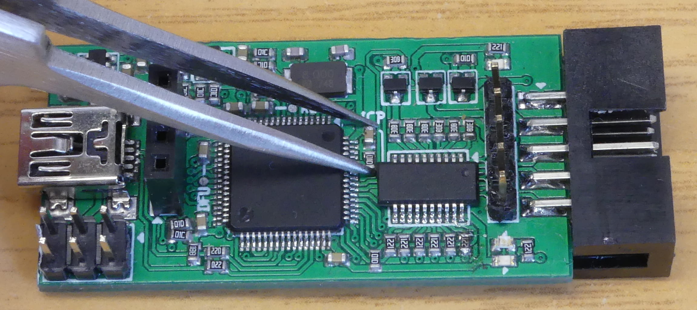
When the UART is started, the power LED should be red while the activity LED should be off.
Connect a USB to UART adapter to the UART pins on the programming port.
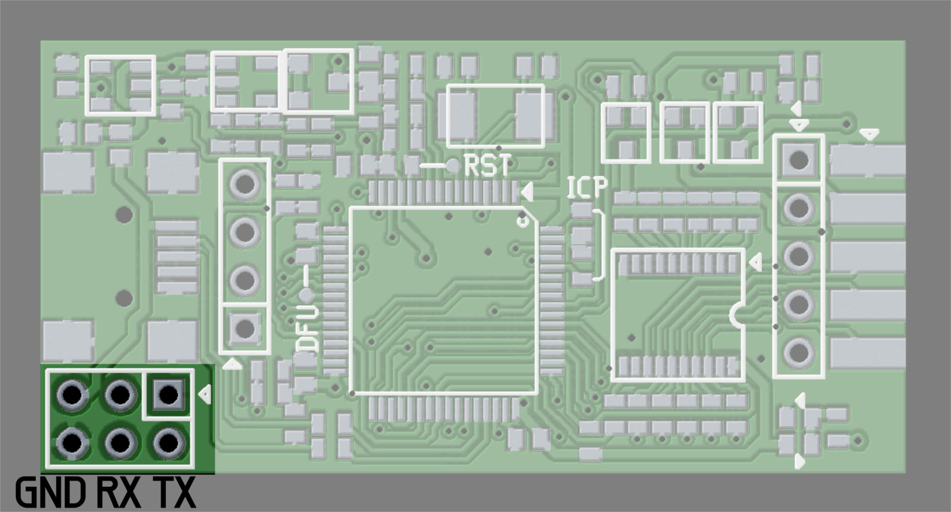
Use stm32flash to flash the bootloader.bin bootloader file from the firmware archive. To do so on Linux run the following command:
stm32flash -w bootloader.bin -v /dev/ttyUSB0
|
Note
|
Alternatively you can use the ST FLASHER-STM32 or stm32loader. |
|
Caution
|
BusVoodoo version 0 has different UART pins and a separate bootloader. |
|
Caution
|
The embedded UART bootloader uses the internal RC oscillator. If this is defective (e.g. part not coming from a trustworthy distributor) this method will not work. |
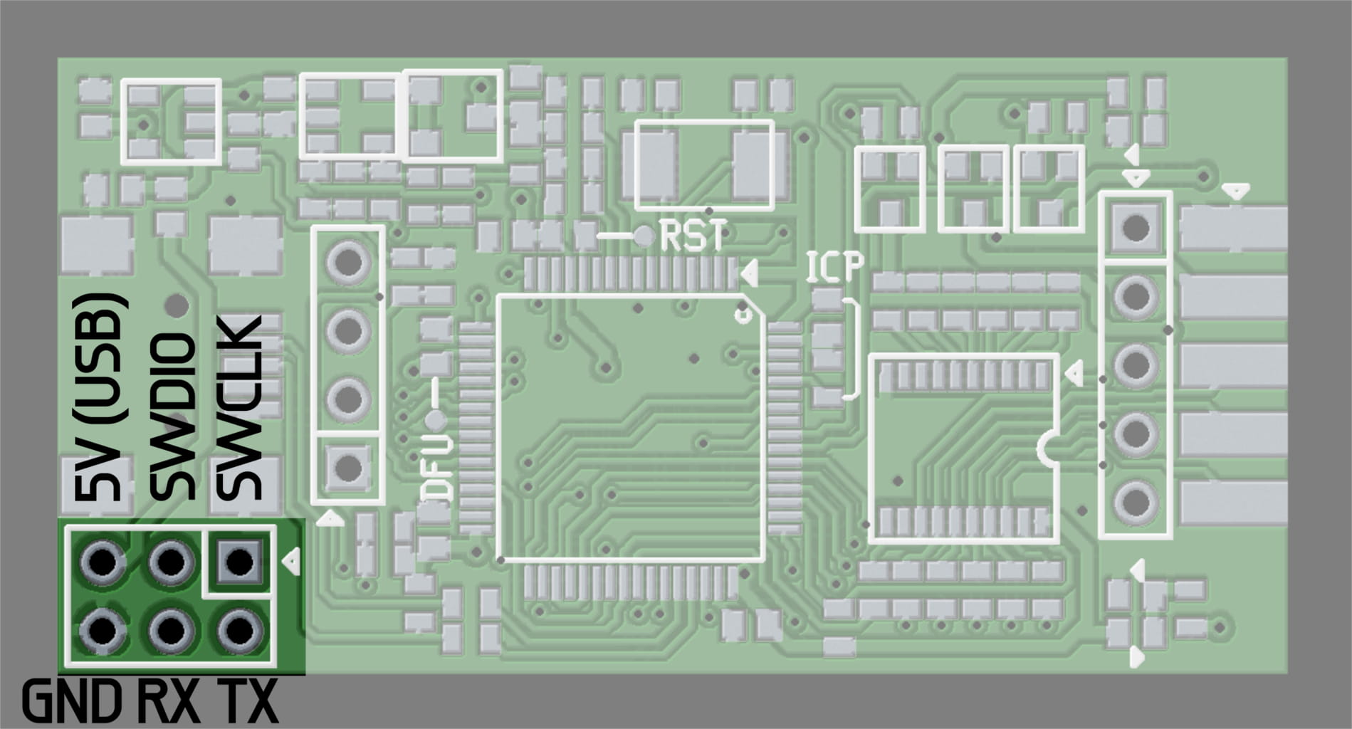
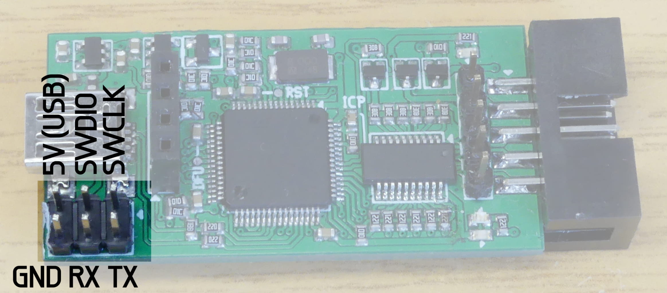
Serial Wire Debug
In case you want to do some firmware development it is recommended to use the Serial Wire Debug (SWD) interface. This allows to easily flash the firmwares and properly debug them.
The SWD pins are available on the programming port.
|
Caution
|
BusVoodoo version 0 has different SWD pins. |
Sometimes after power-up the SWD adapter will not be able to communicate with the micro-controller. Briefly reset the micro-controller by shorting RST test point to ground pad on the nearby capacitor (e.g. using tweezers). From there on communication will always work.
Alternative Firmwares
The BusVoodoo main firmware’s purpose is to play with low-level protocols. While it can be used to perform more complex tasks such as programming chips, it not as easy. For that it is possible to flash alternative firmwares and mimic other debugging adapters. To do so you just need to flash the corresponding alternative firmware. It is always possible to re-flash the original BusVoodoo application firmware later on.
Upcoming alternative firmwares:
-
UART+RS-232 (with hardware flow control) to USB adapter
-
PICkit 2
-
AVR flasher
-
logic analyser (low speed)
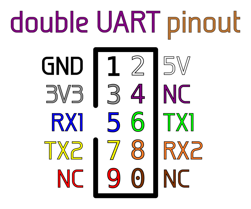
double UART
The probably most used protocol when hacking is UART. Going out of the house without a USB to UART adapter is quite risky. While the BusVoodoo main firmware already supports UART, you sometimes don’t want to configure UART through the built-menu. This is why there had to be a alternative firmware supporting UART (and only that) out of the box. And to top that, this alternative firmware provides two independent UART interfaces. This is ideal to debug two separate devices, by a man-in-the-middle, or convert from one baud rate to another.
The built firmware binary file is available here. Use the normal flashing instructions to flash the firmware. The source code is available here.
|
Note
|
The pins are driven in push-pull mode at 3.3V, but are 5V tolerant. |
|
Warning
|
16-bit words, and mark or space parity are not supported yet. |
|
Caution
|
There is currently no Windows 7 driver available for this firmware. Please contact us if required. |
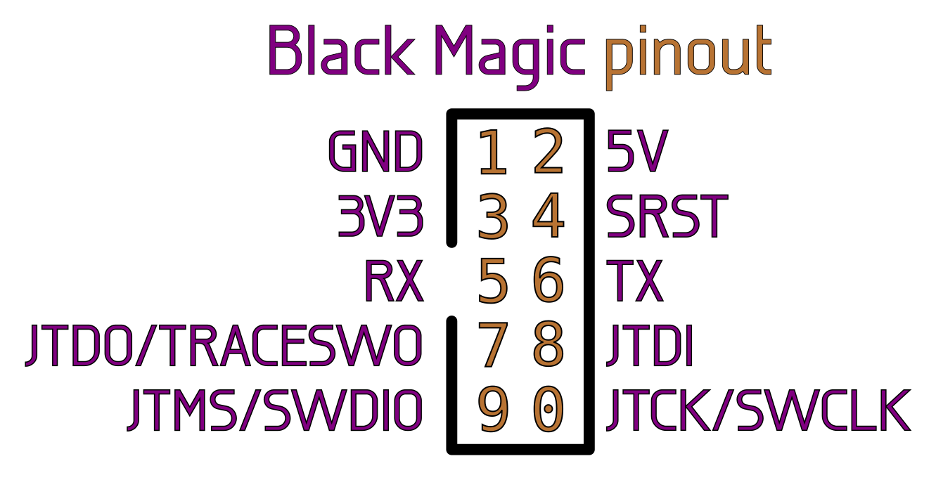
Black Magic Probe
The Black Magic Probe is a JTAG and SWD adapter with embedded GDB server. The Black Magic firmware has been extended to support the BusVoodoo platform.
The built firmware binary file is available here, with flashing instructions in the README file. The source code is available here.
Restrictions compared to the original Black Magic Probe:
-
only supports 3.3V signals (in push-pull mode)
Firmware Development
The development is done under Linux. If you wish to compile the source code yourself you will need the following packages: gcc-arm-none-eabi, binutils-arm-none-eabi, gdb-arm-none-eabi, libnewlib-arm-none-eabi, rake, openocd, doxygen. More details on how to compile and flash the firmware is provided in the README.
|
Tip
|
Instead of using the USB port to connect to the BusVoodoo you can use the UART port available on the programming connector. This allow to stay connected even if the BusVoodoo restarts and resets the USB communication. The UART port is a mirror of the data exchanged over the USB port. The serial configuration is 921600 bps, 8 data bits, no parity, 1 stop bit. |
|
Caution
|
BusVoodoo version 0 has different SWD and UART pins. |
Hardware Development
The files describing the hardware are available here.
Sources
The hardware archive includes following files:
-
BusVoodoo_schematic.pdf: schematic export
-
BusVoodoo_notes.txt: design notes about the schematic
-
BusVoodoo.sch: gEDA gschem schematic
-
BusVoodoo_layout.pdf: board layout export
-
BusVoodoo_layout-*.png: pictures of the board
-
BusVoodoo.*.gbr and BusVoodoo.*.cnc: board fabrication files (gerber and drill)
-
BusVoodoo.pcb: gEDA pcb board layout
-
BusVoodoo_bom.csv and BusVoodoo_costs.csv: the Bill of Material (BOM) and cost estimation
The source files and scripts are available in the git.
Versioning
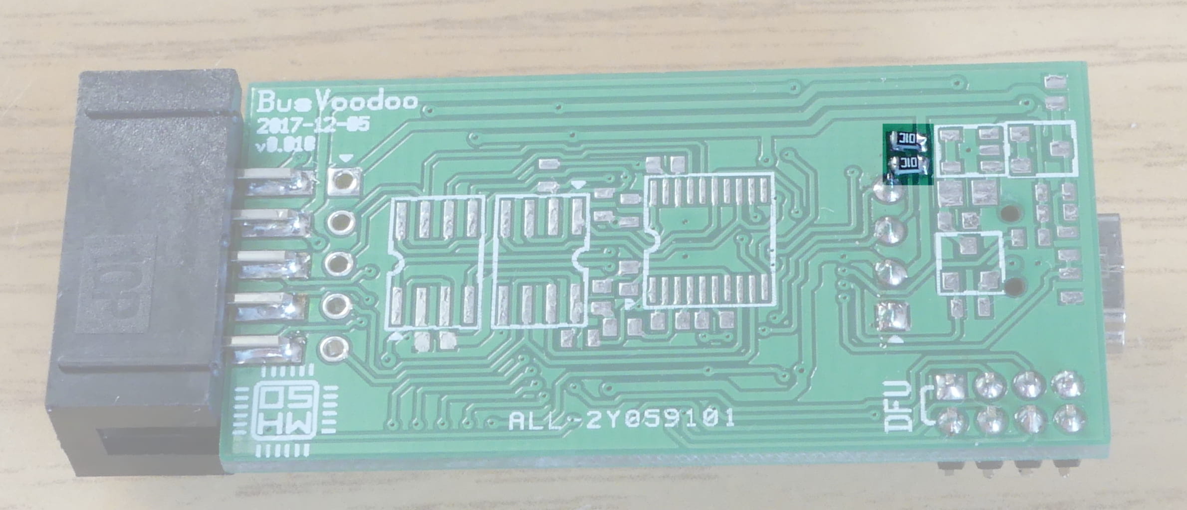
The complete hardware version has the following format: x.yyy, where x is a letter for the major hardware version (or 0 for the prototype), and yyy is the revision. You get the major hardware version by connecting to the BusVoodoo and entering the version command in HiZ mode. The complete hardware version, including the revision, is available on the back of the board.
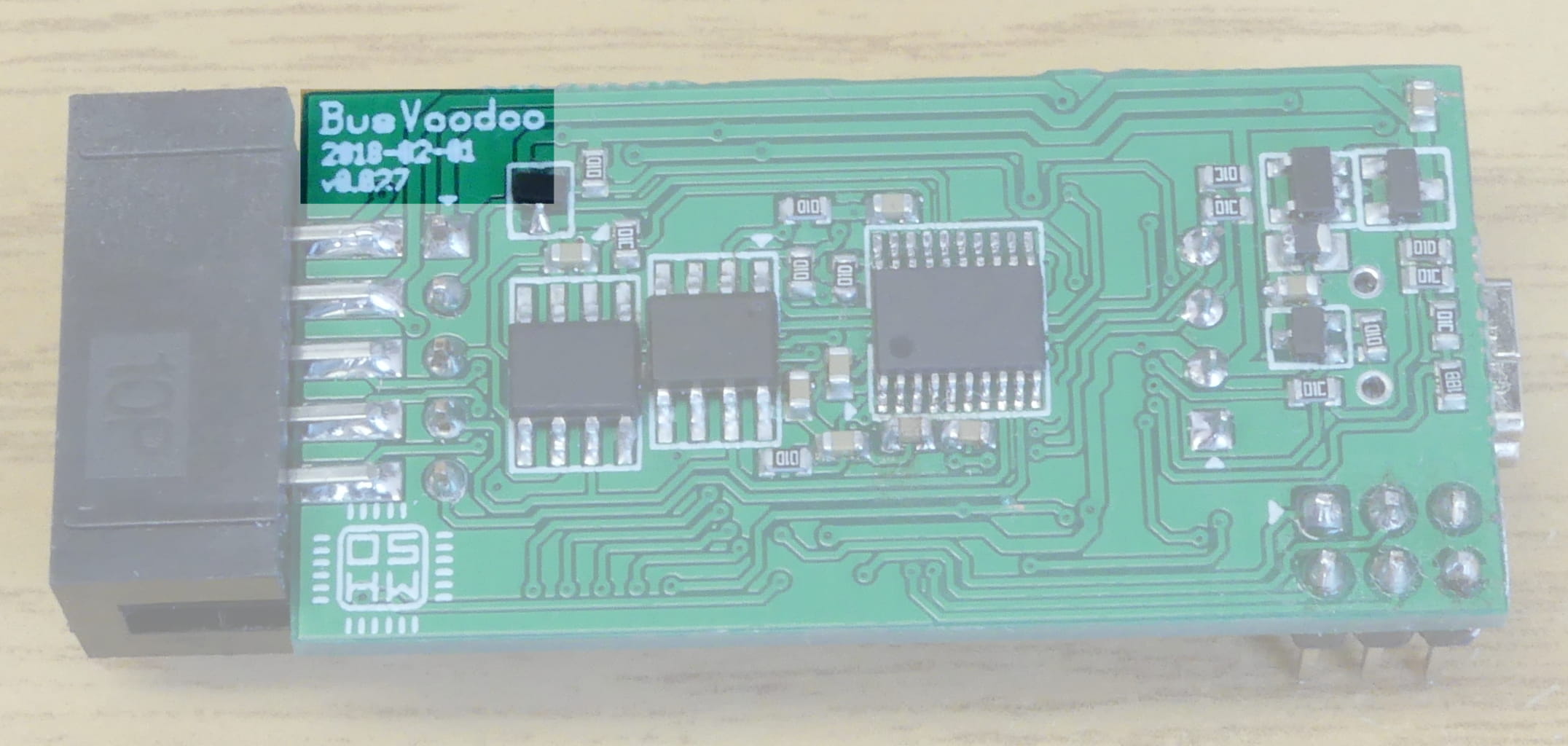
The changes between the major hardware versions is described in CHANGES.txt. The revision is incremental across the major hardware version and corresponds to the number of changes in the schematic and board layout. The changes are described in the git commit log.
BusVoodoo light vs full
The BusVoodoo adapter comes in two flavours: light and full. But both flavours share the same board. The difference is that the components on the back side of the board are not populated. These are the boost voltage regulator for the high voltage and the RS-232, RS-485, and CAN transceivers.
This makes it possible to convert a BusVoodoo light into an BusVoodoo full. The component list is available in the BOM and the placement is described in the board layout. You also have to make the holes in the case to export the RS/CAN and OLED connectors. The firmware is the same and the flavour is detected during boot by checking the presence of the high voltage regulator. The only thing you won’t have is the protocol support.
OLED display
The BusVoodoo full already comes with an OLED display which shows the pinout of the connectors for the current mode. Since the board is common to the light and full flavour, the OLED display can be added to the BusVoodoo light. To perform this modification you will need to solder two SMD resistors next to the OLED connector (2 to 10 kOhm, in 1608 metric/0603 imperial surface mount package). The display is a common 0.96 inch I²C OLED display (details are available in the BOM).
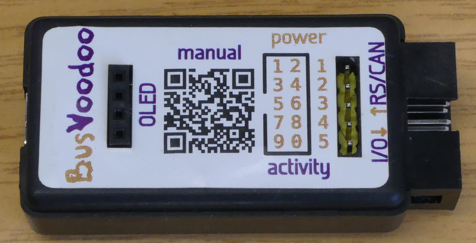
The sticker on the case indicates where you need to make a hole in the case so the display can be connected to the board. You can solder the pins of the OLED display directly on the board, but this will block the access to the programming port. Instead, it is recommended to solder a female 1x4-pin header on the board (details are available in the BOM).
Testing
In case you built the BusVoodoo hardware by yourself, use the following test procedure to verify if the board is in a working state:
-
Using the continuity test on a multimeter ensure there are no shorts on the power rails:
-
test across the 5V USB and ground pins on the bottom right programming connector on the front side of the board
-
test across the 3.3V and ground pads of the top left capacitor on the front side of the board
-
test across the low voltage and ground pads of the top middle capacitor on the front side of the board
-
test across the high voltage and ground pads of the top right capacitor on the back side of the board
-
-
Connect the board to a 5V power supply with current limit set to 50 mA using the programming or USB port. Only the red power LED should light up, and the board should draw around 11 mA.
-
Connect an SWD adapter to the programming port and erase the flash. This will check proper SWD connectivity to the micro-controller, and a working micro-controller. Here the command using the Black Magic Probe:
arm-none-eabi-gdb --eval-command='target extended-remote /dev/ttyACM0' --eval-command='set confirm off' --eval-command='monitor swdp_scan' --eval-command='attach 1' --eval-command='monitor erase' --eval-command='monitor erase_mass' --eval-command='quit'
-
Connect an UART adapter to the programming and flash the bootloader using the UART bootloader. This will check proper UART connectivity to the micro-controller and UART bootloader. Here the command using stm32flash:
stm32flash -w bootloader.bin -v /dev/ttyUSB0
-
When re-plugged to power, both power and activity red LEDs should be on.
-
When plugged into USB it should be recognized as USB device:
-
The USB VID:PID is 1209:4256.
-
Using lsusb you will see the name InterBiometrics. This corresponds to the name of the vendor the VID as been allocated to. BusVoodoo uses a PID generously allocated by pid.codes.
-
Using sudo lsusb -v -d 1209:4256 you should see the following (excerpt):
  idVendor           0x1209 InterBiometrics
  idProduct          0x4256
...
  iManufacturer           1 CuVoodoo
  iProduct                2 BusVoodoo multi-protocol debugging adapter
...
      bInterfaceClass       254 Application Specific Interface
      bInterfaceSubClass      1 Device Firmware Update
      bInterfaceProtocol      2
      iInterface              3 DFU bootloader (DFU mode)
-
-
Flash the device using DFU bootloader:
sudo dfu-util --device 1209:4256 --download application.bin
-
Now the activity LED should be blue, indicating the application firmware booted correctly. Using sudo lsusb -v -d 1209:4256 you should see the following (excerpt):
idVendor 0x1209 InterBiometrics idProduct 0x4256 ... iManufacturer 1 CuVoodoo iProduct 2 BusVoodoo multi-protocol debugging adapter ... bInterfaceClass 254 Application Specific Interface bInterfaceSubClass 1 Device Firmware Update bInterfaceProtocol 1 iInterface 3 DFU bootloader (runtime mode) -
If present the OLED screen should be switched on and display HiZ along with the pinout.
-
Force the DFU bootloader to ensure it works. No need to re-flash the device once you force the DFU mode. Re-powering the BusVoodoo will boot back the application.
-
Connect to the BusVoodoo in the default HiZ mode, remove all cables from the I/O and RS/CAN ports, and run the self-test using the self-test command. This will ensure that electronic component pins are connected to the board.
-
Connect to the BusVoodoo in the default HiZ mode, remove all cables from the I/O and RS/CAN ports, run the pins-test using the pins-test command, and follow the instructions. This will ensure that I/O and RS/CAN pins are connected to the board.
-
If all went fine until here, you have a working BusVoodoo hardware. All other issues are most likely coming from the firmware.
Version 0
BusVoodoo hardware version 0 was the prototype for the BusVoodoo, and only distributed to reviewers. The major differences to version A is that it does not support CAN (due to a design flaw), and has a different programming port (2x5-pin, 2 mm pitch).
This results in some changes:
-
the application and bootloader firmwares can be found in this firmware archive
-
to start the DFU bootloader short the DFU pin on the programming connector to the adjacent 5V pin
Support
Reporting Issues
If you find any issue, please contact us to report it. Before reporting an issue ensure that you have flashed the latest firmware.
When reporting an issue, include the following information:
-
BusVoodoo hardware and software version (connect to the BusVoodoo and enter the version command in HiZ mode to get it)
-
what you intend to do
-
what you did
-
what you expected
-
what happened
-
if the issue is in the communication with target hardware, please also provide an electrical trace (e.g. using sigrok)
-
any additional information is welcome
|
Note
|
Be sure the answer is not already included in this manual. Use CTRL+F to help you finding the corresponding information. |
|
Tip
|
A Logic Analyser (8 channels, 24 MHz) is provided with the BusVoodoo full. This can be used with sigrok. While the device appears as a Saleae Logic 8, it is merely a clone, and not a genuine Saleae device. Thus it would not be fair to use their software. |
Requesting Features
The BusVoodoo full comes with protocol support. If there is a protocol you wish to be added supported, or a missing feature to be implemented, you can contact us and request it (within the capabilities of the hardware).
When contacting us also include the board ID which can be retrieved by connecting to the BusVoodoo and entering the version command in HiZ mode. This is only used to ensure that you actually bought a BusVoodoo full with protocol support. If this is not the case you can still contact us, but the request won’t have the same priority.
We keep the right to include the additional feature or protocol support in the public BusVoodoo firmware. Teaching about general electric aspects or explaining how protocols work is outside of the protocol support scope.
Alternatives
The BusVoodoo is not the first and only device to debug multiple protocols. Probably every hardware hacker develops his own solution at some point, using parts he is familiar with, and suited for the tasks his is struggling with. And there probably never will be a perfect device capable of everything since the needs are different, but a bit of help is always welcome.
The closest alternative to the BusVoodoo is probably the Bus Pirate, and this is actually the device I used for a long time before I decided to make my own because shortcomings piled up. The name BusVoodoo is also inspired from the Bus Pirate and is an homage to it, and the more I develop the BusVoodoo the more I learn about the Bus Pirate and appreciate it. I also wanted my device to come in a nice small rigid case, and for that I am using the case of USB Blaster JTAG adapter clones.
Advantages of the Bus Pirate over the BusVoodoo:
-
it is a mature product (v3 is, v4 isn’t)
-
it supports the most common protocols
-
it is cheap ($30) and readily available
Advantages of the BusVoodoo over the Bus Pirate:
-
it uses a native USB interface instead of a USB to UART chip, allowing for greater speeds and to be flashed as other devices. The Bus Pirate v4 also comes with native USB, but it never reached maturity
-
it has an adjustable voltage regulator, also used for the embedded pull-up resistors, allowing 1.6-5.0V logic
-
it supports more protocols in hardware (eMMC, SMBus, I2S, …)
-
it supports other protocols in software
-
it supports non-TTL/CMOS protocols: RS-232, RS-485, RS-422, and CAN (only on the full flavour)
-
no need to always have the Bus Pirate connector description at hand as the BusVoodoo shows the pinout within the menu and on the OLED screen (only on the full flavour)
-
it comes in a nice and compact case (and some other accessories like USB cable and I/O jumper cable)
-
it supports CTRL+C and CTRL+D on top of the VT-100 commands
-
and probably the most important aspect: it is actively developed and has user support
The Bus Pirate and BusVoodoo are only designed for low speed protocols (< 20 MHz). The GreatFET supports high speed protocols, but has not yet been released. And there is the Datenkrake for even higher speed protocols (using an FPGA), but is also more of a development board than a ready to use tool.
BusVoodoo will never replace dedicated tools (USB to UART dongle, JTAG adapter, flash programmer, …) or prevent from using a development board to control all nifty protocol details, but it is a convenient quick all-in-one first approach tool.